How ArUco Codes Work
One way to create an augmented reality application is through a AR marker; when your device’s camera detects the marker, it can figure out the relative orientation and position to the marker, and use that, in turn to draw dynamic 3D models on it.
It can look a little bit like this:
So, how does it work?
“Any sufficiently advanced technology is indistinguishable from magic”
Arthur C. Clark
Let’s see if we can pull back the curtain.
Overview
- Images from the webcam are processed.
- Corners of objects are detected.
- The edges are formed into polygons; if they aren’t roughly square, they are rejected.
- Each square object is analyzed; it is projected onto a smaller square, and then checked to see if it matches a known AR code.
- If a marker is determined, then it is looked at in the original image more closely to try to find out very accurately where the corners are.
- Using the 2d position of the marker and its corners, a 3d position for an object can be estimated — and I just need to draw an object there.
At a high level, the following things happen:
What is really neat about this is that it isn’t just good for overlaying whimsical items in 3d, it is also useful for a robot navigating a room to know where it is, or for obtaining clear data for how an object is positioned in space (which is useful for creating a ballot scanner, for example).
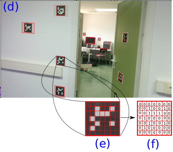
Here is how the ‘big picture’ overview of the process is described in the paper, “Speeded Up Detection of Squared Fiducial Markers.”:
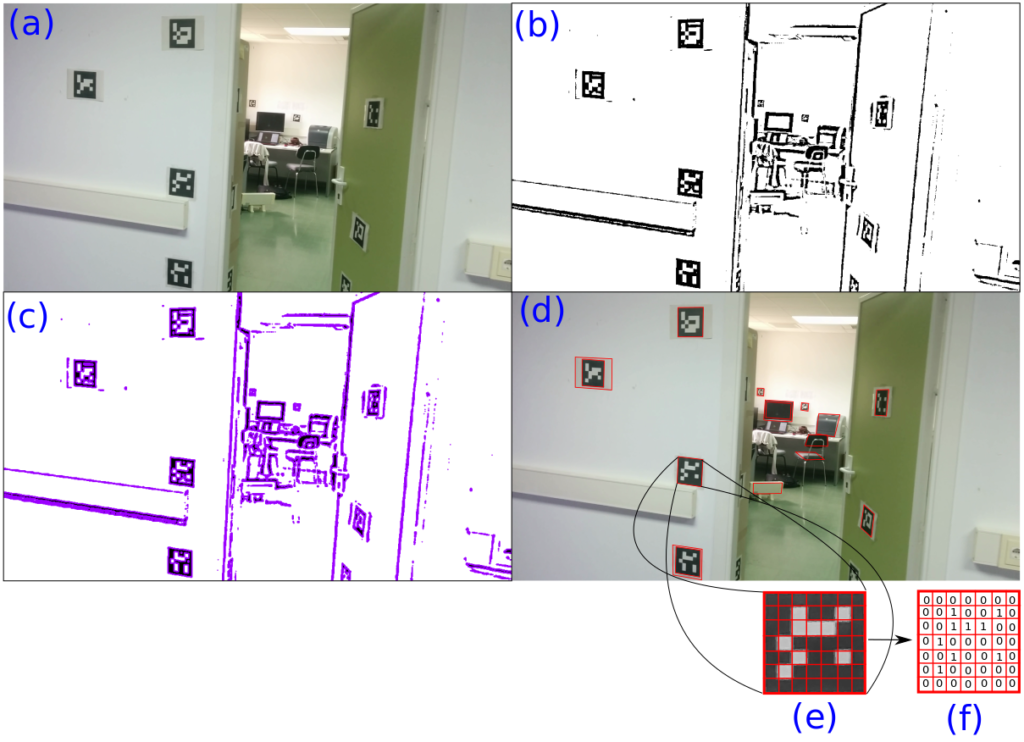
Figure 1: Detection and identification pipeline of ArUco.
(a) Original image.(b) Image thresholded using an adaptive method. (c) Contours extracted. (d) Filtered contours that approximate to four-corner polygons. (e) Canonical image computed for one of the squared contours detected. (f) Binarization after applying Otsu’s method.
from “Speeded Up Detection of Squared Fiducial Markers”
Limitations:
There are a couple of limitations to this approach:
- It is processor intensive. It takes a lot of work to scan an image!
- It needs strong black and white contrast. In the video above, you’ll see that sometimes the objects disappear; that is because the camera is moving the the codes become blurry, making it impossible to accurately detect where the corners are.
Let’s dive in deeper!
Much of the information for this pages comes from the ArUco website, and their paper, “Speeded Up Detection of Squared Fiducial Markers.”
Images Come From A Webcam
A computer stores everything as numbers (just 0s and 1s). Images tend to be a grid (a 2D array) of numbers, with a set of numbers representing the color.
Human eyes have three varieties of cells called ‘cones’ that are sensitive to light in different colors; when you add red light, green light, and blue light in different quantities, you can make up almost any color. That’s why the color picker on your computer lets you mix red, green, and blue.
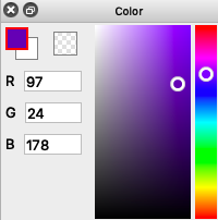
The Red, Green, and Blue values (RGB for short) are typically stored as one byte each; a byte holds a number from 0 to 255, and is sometimes represented as a base 16 number (called a hexadecimal), from binary 0b0000-0000 (0x00 in hexadecimal) to 0b1111-1111 (0xFF).
If you’ve created web pages, you may have seen colors represented as RGB triplets; for example, #FF0000 would represent full red, no green, and no blue.
Let’s suppose then that we have an initial, ‘input’ image like this:

Incidentally, if you were to download that image and save it as a png, you could load and show it using Python and OpenCV as follows (but not that getting the OpenCV libraries, or python for that matter, is beyond the scope of this article!):
# based on https://pythonprogramming.net/loading-images-python-opencv-tutorial/

import cv2

img = cv2.imread('InputImage.png')
cv2.imshow('image',img)
cv2.waitKey(0)
cv2.destroyAllWindows()
Enter The Matrix

In many computational environments, an image would be simply stored as a two-dimensional array. In the Open Computer Vision library (OpenCV for short), it is stored in a matrix. (The class name for a matrix is Mat, and you have one matrix, but two matrices).
Matrices are used for some of the following, very different things:
- to represent images
- to transform points
- to solve systems of equations
Okay, it’s time to go back to a higher level.
Detecting Corners
I really wanted to figure this one out, but by golly, the Harris Corner detection algorithm from 1988 uses calculus and matrix math and was just a bit too much for me to understand, much less simplify.
So, I’m going to leave it as ‘magic’, but, here’s a nice video about it:
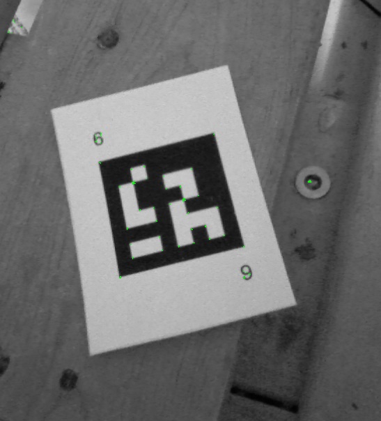
Here is what our input image looks like when we run the Harris Corner detector:
And here is some python code to do it:
# based on https://docs.opencv.org/3.0-beta/doc/py_tutorials/py_feature2d/py_features_harris/py_features_harris.html

import cv2
import numpy as np

# Load the image, make it greyscale
color_image = cv2.imread('InputImage.png')
grey_image = cv2.cvtColor(color_image, cv2.COLOR_BGR2GRAY)

# Detect corners
intensity_field = np.float32(grey_image)
corner_image = cv2.cornerHarris(intensity_field, 2,3,0.04)

# Draw the corners onto our grey image, in green
# The number of corners shown changes based on the threshold
threshold = 0.05 * corner_image.max()
final_image = cv2.cvtColor(grey_image, cv2.COLOR_GRAY2BGR);
final_image[corner_image > threshold] = [0, 255, 0]

# Save or display the image
# cv2.imwrite('Corners.png', final_image)
cv2.imshow('corners',final_image)
if cv2.waitKey(0) & 0xff == 27:
    cv2.destroyAllWindows()
Finding Polygons
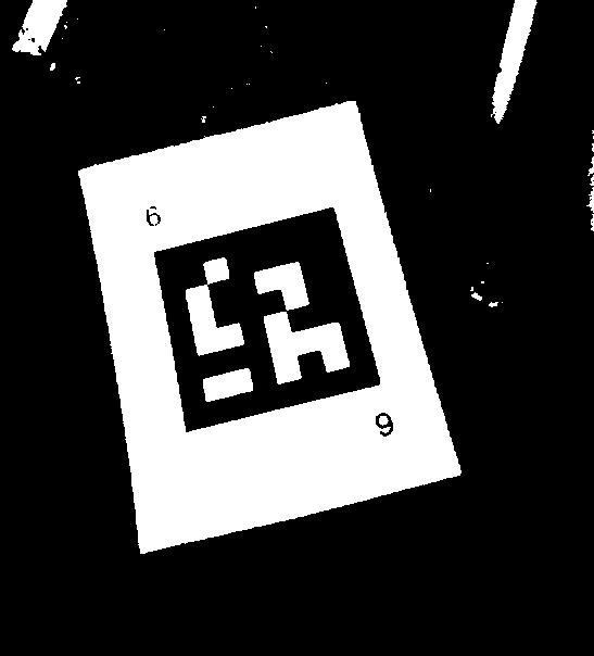
At some point, the image is converted to a greyscale image, and then is turned into a black and white image.
The simplest way of turning a greyscale image (where each pixel is represented by one number, the intensity, usually in the range of 0 to 255) into a black and white ‘binary’ image is to use a threshold value. For example, say we use a value of 128 for our threshold; every pixel that is darker than the threshold (ie. pixel intensity < 128) is now black (0), and every other pixel becomes white (1).
Here’s our binary image with a simple global threshold applied:
[Often a more advanced technique is used called ‘adaptive thresholding’. In this technique, a rectangle (a ‘window’) around the current pixel is examined, and the average intensity is calculated. If the current pixel is darker than the average, it becomes black; otherwise, it becomes white. This works really nicely on, say, a photograph of a book where the page is unevenly lit. A simple threshold is likely to turn a large part of the page black. Here are some pictures].
Now, with a monochrome or ‘binary’ image, we can use a ‘border following’ technique published in 1985. While I haven’t read the paper yet, I imagine it is a lot like doing line following on a robot.
We then follow the borders from each edge, and where they connect, form polygons. We can then tally up the length of the borders between the edge to find a perimeter, and clever people have devised a way to simplify the outline, reducing it to a polygon. If it reduces nicely to a polygon with four edges, and the lengths of the edges are somewhat similar, it is a candidate to process further and see if we can detect an ArUco fiduciary marker.
Do We Have A Marker?
Once we have a plausibly square area with four corners, we can project the image inside it into a square, and then take a look at it. First, let’s take a look at a final image with a marker detected:
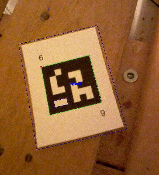
In the picture, the detected markers (all one of them!) are shown with a green border and they have an id code shown in blue. I’ve taken the list of ‘rejected’ points and drawn squares in dark blue — you can see one around the card and a very small one above it.
Here’s code to do it:
# based on https://mecaruco2.readthedocs.io/en/latest/notebooks_rst/Aruco/aruco_basics.html

import cv2
from cv2 import aruco

frame = cv2.imread("InputImage.png")

grey = cv2.cvtColor(frame, cv2.COLOR_BGR2GRAY)
aruco_dict = aruco.Dictionary_get(aruco.DICT_6X6_250)
parameters =  aruco.DetectorParameters_create()
corners, ids, rejectedImgPoints = aruco.detectMarkers(grey, aruco_dict, parameters=parameters)
frame_markers = aruco.drawDetectedMarkers(frame.copy(), corners, ids)

# draw the rejected candidates
for rejectedPolygons in rejectedImgPoints:
    for points in rejectedPolygons:
        cv2.line(frame_markers, tuple(points[0]), tuple(points[1]), [200, 0, 0])
        cv2.line(frame_markers, tuple(points[2]), tuple(points[1]), [200, 0, 0])
        cv2.line(frame_markers, tuple(points[2]), tuple(points[3]), [200, 0, 0])
        cv2.line(frame_markers, tuple(points[0]), tuple(points[3]), [200, 0, 0])

# Save or show the image
cv2.imwrite('Marker.png', frame_markers)
cv2.imshow('marker', frame_markers)
if cv2.waitKey(0) & 0xff == 27:
    cv2.destroyAllWindows()
So, how do we go from a list of polygons that potentially show a fiduciary marker to a list of markers and rejected polygons?
The best way to describe it is to use one of the images from the speeding up ArUco paper:
Each polygon that is potentially a marker is projected into a square (from the binary image). Apparently, 32×32 pixels works reasonably well for the square size. Then, each of the pixels in each cell is examined; if they are mostly black, the final result is a 0; otherwise, it is a 1. This is recorded into a 2D array at the right size for the markers we are looking for. [The codes in the image use a 5×5 grid with a black border, so the target image size is 7×7].
The result is then compared to all of the possible markers in the dictionary we are using, rotated 0, 90, 180, and 270 degrees. [Think of the dictionary as being a list of ‘words’ that are should be understood.] Also, and I haven’t looked up the details, but the markers have been designed to allow for some bits to be incorrectly interpreted, but still get the correct results. (Wow!)
With that done, the scaled down image is either accepted as being a known marker, or rejected. (Any code you wrote that called aruco.DetectMakers() gets a list of ids and corners, and a list of rejected polygons).
Now What?
Once you know where the markers are, you can do things with them. What is really interesting is that if you know how large the markers are (say in inches or centimeters), you can tell where the camera is in relation to the marker. [You can do this with additional accuracy if you calibrate the camera first — and the ArUco library provides a way to do this.]
Knowing where they stand in relation to each other allow you to do things, such as:
- render a 3D object on top of the marker, in the correct perspective, as though it was really there [Augumented Reality]
- help a robot navigate an indoor space
- it could also be used to help a person with a smartphone app navigate an indoor space, like indoor-GPS; this might be useful in a museum, school, or warehouse.
How Do I Get Started?
If you want to write code to detect ArUco markers, there are several approaches. OpenCV and Aruco are written in C++, but there are wrappers to use it from many popular languages.
- If you know C++, your easiest bet is to use OpenFrameworks, which calls itself “openFrameworks is an open source C++ toolkit for creative coding”.
- Python is used a lot for vision processing and machine learning. It isn’t trivial to set up (google is your friend), but is a simple way forward once it is working.
- I’m using C# with Unity and purchased a $100 asset called “OpenCV for Unity“. You have to adapt code written in other languages, but it seems pretty nice. (Now, I wish I could just use version 3 of the ArUco library with it).
- There is an OpenCV integration for Java and even Javascript (which blows my mind just a little bit).
- For something a little simpler, especially if you are familiar with Processing, there’s an OpenCV plugin for Processing.
Leave a Reply